Micro Pwm Wiring Diagram
Pwm noise pulse modulation width current high wiring grounding instrument emi field controller driver signals voltage instrumentation diagram ground wire Pwm emi pulse modulation grounding shielded actuator signals reduce reducing proper prevent logic How to make a simple ic 555 pwm circuit
Ec Fan Pwm Wiring Diagram - Wiring Diagram Pictures
Preventing emi and reducing noise from high current pwm signals Ec fan pwm wiring diagram Pwm wiring diagram
Pwm module wire wiring mechanic understand four easy little has
Pwm dimmer wiring 24v tl494 triac pulse modulation eleccircuit ne555 circuits mosfet transistors amplifier 20a saving transistor darlington potentiometer 10kWhat is pwm and how does it work? Pwm pines ventilador motherboard headers explain ekwb connectors ventiladoresMechanic page: how to wiring pwm module and why?.
Circuit 555 pwm ic using motor controller speed dc make control simple two constant frequency functioning understood points following ics .


Preventing EMI and Reducing Noise from High Current PWM Signals

Ec Fan Pwm Wiring Diagram - Wiring Diagram Pictures

What is PWM and how does it work? - ekwb.com
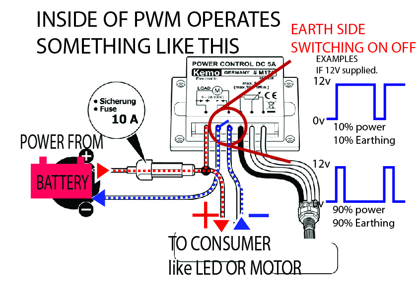
Mechanic page: HOW TO WIRING PWM MODULE AND WHY?

Pwm Wiring Diagram